Steps
1. Unroll the required length of network cable and add a little extra, just in case. If a boot is to be fitted, do so before stripping away the sleeve and ensure the boot faces the correct way.
2.
Carefully remove the outer jacket of the cable, exposing about 1 1/4" (30 mm) of the twisted pairs. Be careful when stripping the jacket as to not nick or cut the internal wiring. After removing the outer case, you will notice 8 wires twisted in 4 pairs. Each pair will have one wire of a certain color and another wire that is white with a colored stripe matching its partner (this wire is called a tracer). Sometimes a rip cord (white thread) is also present.
3.
Inspect the newly revealed wires for any cuts or scrapes that expose the copper wire inside. If you have breached the protective sheath of any wire, you will need to cut the entire segment of wires off and start over at step one. Exposed copper wire will lead to cross-talk, poor performance or no connectivity at all. It is important that the jacket for all network cables remains intact.
4.
Untwist the pairs so they will lay flat between your fingers. The white piece of thread can be cut off even with the jacket and disposed (see Warnings). For easier handling, cut the wires so that they are 3/4" (19 mm) long from the base of the jacket.
5.
Arrange the wires based on the wiring specifications you are following. There are two methods set by the TIA, 568A and 568B. Which one you use will depend on what is being connected. A straight-through cable is used to connect two different-layer devices (e.g. a hub and a PC). Two like devices normally require a cross-over cable. The difference between the two is that a straight-through cable has both ends wired identically, while a cross-over cable has one end wired 568A and the other end wired 568B.[1] For our demonstration in the following steps, we will use 568B, but the instructions can easily be adapted to 568A.
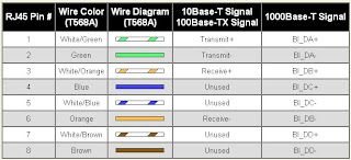
o 568B - Put the wires in the following order, from left to right:
white orange
orange
white green
blue
white blue
green
white brown
brown
o 568A - from left to right: white/green, green, white/orange, blue, white/blue, orange, white/brown, brown. You can also use the mnemonic 1-2-3-6/3-6-1-2 to remember which wires are switched.
6. Press all the wires flat and parallel between your thumb and forefinger. Verify the colors have remained in the correct order. Cut the top of the wires even with one another so that they are 1/2" (12.5 mm) long from the base of the jacket, as the jacket needs to go into the 8P8C connector by about 1/8", meaning that you only have a 1/2" of room for the individual cables. Leaving more than 1/2" untwisted can jeopardize connectivity and quality. Ensure that the cut leaves the wires even and clean; failure to do so may cause the wire not to make contact inside the jack and could lead to wrongly guided cores inside the plug.
7.
Keep the wires flat and in order as you push them into the RJ-45 plug with the flat surface of the plug on top. The white/orange wire should be on the left if you're looking down at the jack. You can tell if all the wires made it into the jack and maintain their positions by looking head-on at the plug. You should be able to see a wire located in each hole, as seen at the bottom right. You may have to use a little effort to push the pairs firmly into the plug. The cabling jacket should also enter the rear of the jack about 1/4" (6 mm) to help secure the cable once the plug is crimped. You may need to stretch the sleeve to the proper length. Verify that the sequence is still correct before crimping.
8.
Place the wired plug into the crimping tool. Give the handle a firm squeeze. You should hear a ratcheting noise as you continue. Once you have completed the crimp, the handle will reset to the open position. To ensure all pins are set, some prefer to double-crimp by repeating this step.
9. Repeat all of the above steps with the other end of the cable. The way you wire the other end (568A or 568B) will depend on whether you're making a straight-through, rollover, or cross-over cable (see Tips).
10.
Test the cable to ensure that it will function in the field. Mis-wired and incomplete network cables could lead to headaches down the road. In addition, with power-over-Ethernet (PoE) making its way into the market place, crossed wire pairs could lead to physical damage of computers or phone system equipment, making it even more crucial that the pairs are in the correct order. A simple cable tester can quickly verify that information for you. Should you not have a network cable tester on hand, simply test connectivity pin to pin.
Straight-Through Cable Pin Out for T568A

Straight-Through Cable Pin Out for T568B
2 standard:
1) EIA/TIA 568A (American)
2) EIA/TIA 568B (British)
EIA- Electronic Industry Association
TIA- Telecomunication Industry Association
Unshielded Twisted Pair:


for telecommunication
-telefon
-internet
-PC 2 PC
-Point 2 Point
-Node 2 node
Shielded Twisted pair
 Coaxial Cable

A:Plastic Jacket
B: Metallic Core
C: Dialetric Insulator
D: Center Core
for CCTV&TV
Fiber Optic Cat 5
Cat 5
commonly known as Cat 5 or "Cable and Telephone", is a twister pair cable type designed for high signal integrity.
Cat 5: Currently unrecognized by TIA/EIA. Provided performance of up to 100 MHz, and was frequently used on 100 Mbit/s Ethernet networks. May be unsuitable for 1000BASE-T gigabit ethernet.
Cat 5e: Currently defined in TIA/EIA-568-B. Provides performance of up to 100 MHz, and is frequently used for both 100 Mbit/s and Gigabit Ethernet networks.


